Building an Analog Repressilator

Table of Contents
Introduction
Each light represents a neuron.
The repressilator is a simple circuit where we create a ring of three inhibitory neurons that repress each other. While this architecture is famously used in synthetic biology to create oscillations in gene expression, here we implement it using analog electronics.

Three inhibitory neurons in a cyclic inhibitory ring.
Circuit
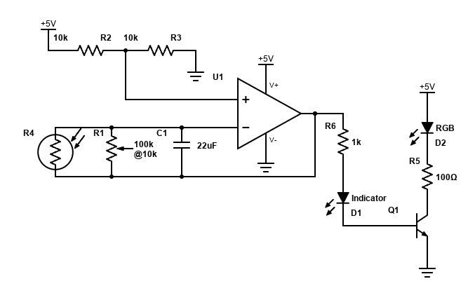
Circuit for a single neuron that is inhibited when light shines on the LDR.
We use a simple inverting integrator with a time constant tuned to roughly half a second. The indicator LED ensures the transistor fires in the expected range, it could likely be replaced by adjusting R6. The LED D2 shines on the next neuron in the chain to inhibit it.
To build the repressilator, connect an odd number of these neurons in a ring. Use a hot glue stick as a light pipe to channel the light from each LED directly to the next neuron’s LDR. The number must be odd otherwise we create a bistable circuit that does not oscillate (the system gets stuck with half the lights on and half off).
Behaviour
This circuit is a physical manifestation of a limit cycle, meaning a cyclic behaviour that goes on and on. The dynamics are dependent on ambient light:
High Inhibition: With too much ambient light, the system settles into a stable fixed point where all LEDs remain lit a little bit.
Low Inhibition: With low ambient light, the periodic “heartbeat” rhythm starts as the system begins to oscillate.
In the transition between these states, the system undergoes a supercritical hopf bifurcation.